Highlight:
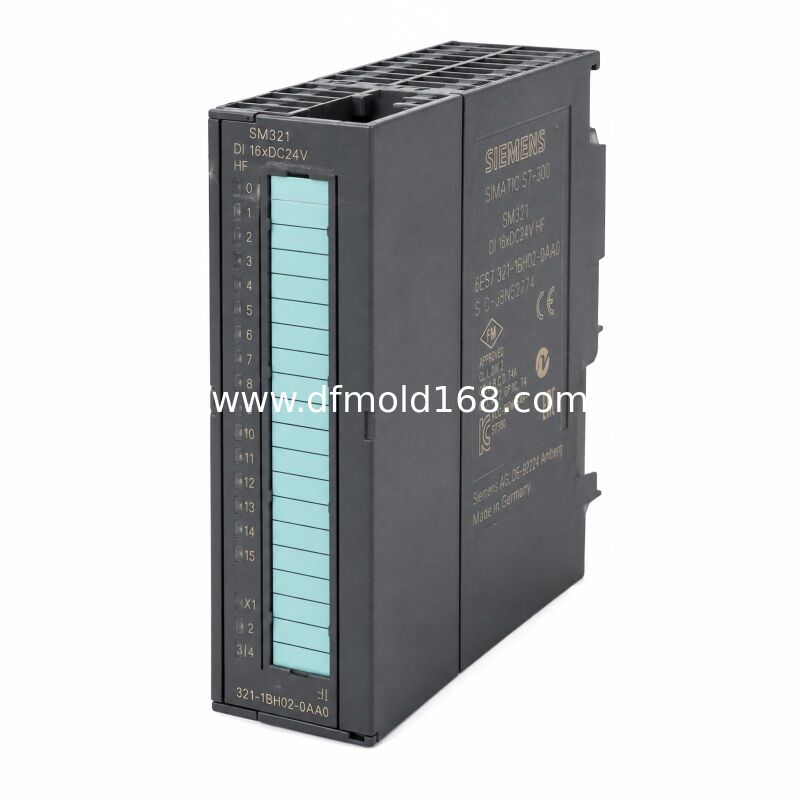
6ES7321-1BH02-0AA0 S7-300 SM 321 Digital Input Module 16DI 24V DC
The 6ES7321-1BH02-0AA0 is an S7-300 SM 321 digital input module designed to connect sixteen 24 V DC field signals to an S7-300 programmable controller.
It receives switching signals from sensors, selector switches, push buttons, limit switches and machine contacts, and transfers their input states to the PLC through the S7-300 backplane bus.
All sixteen inputs form one electrically isolated input group. This separates the field-side input circuit from the internal PLC backplane electronics.
The module uses one 20-pole front connector for field wiring and occupies a standard 40 mm position on an S7-300 mounting rail.
This product is a standard digital input module. It is not a fail-safe F-DI module, servo controller, motor driver or power-supply module.
Because the product has been cancelled, its main application is exact replacement in machines that still operate with an existing S7-300 hardware configuration.
Key Features
- Sixteen 24 V DC digital inputs
- One isolated group of sixteen channels
- IEC 61131 Type 1 input characteristic
- One 20-pole front connector
- Standard S7-300 backplane integration
- LED indication for input states
- 40 mm module width
- Suitable for existing S7-300 maintenance
- Cancelled product supplied as a spare part
Typical Applications
- Limit-switch monitoring
- Proximity-sensor inputs
- Push-button stations
- Conveyor status detection
- Legacy machine control panels
Sixteen Digital Input Channels
The 6ES7321-1BH02-0AA0 provides sixteen channels for detecting 24 V DC switching signals.
Typical field devices include:
- Inductive proximity sensors
- Photoelectric sensors
- Mechanical limit switches
- Selector switches
- Push buttons
- Relay contacts
- Machine-ready signals
- Alarm contacts
The module only reads input states. It does not supply output power to actuators.
24 V DC Input System
The rated input voltage is 24 V DC.
The permitted load-voltage range is:
Lower Limit
20.4 V DC
Upper Limit
28.8 V DC
The field power supply must remain within the permitted range for reliable signal recognition.
Electrical Isolation
The digital inputs are electrically isolated from the PLC backplane electronics.
The sixteen inputs are arranged as one common isolation group.
This means:
- The field circuit is isolated from the internal backplane bus
- The channels are not individually isolated from one another
- The inputs share the same group-level reference arrangement
This distinction is important when planning grounding, potential groups and field wiring.
IEC 61131 Type 1 Inputs
The input characteristic complies with IEC 61131 Type 1.
This makes the module suitable for common industrial 24 V DC switching devices.
According to official data, the signal-zero input-voltage range extends from minus 30 V to plus 5 V.
Field-device compatibility should still be verified according to:
- Sensor output type
- Leakage current
- Cable length
- Grounding arrangement
- Electrical noise
- Input switching frequency
20-Pole Front Connector
The module uses one 20-pole front connector.
The front connector allows field wiring to remain organized and helps simplify replacement of the electronics module.
Before replacement, verify:
- Connector type
- Terminal numbering
- Existing wire labels
- Load-voltage connection
- Common reference terminals
- Mechanical coding
The front connector may not be included with every replacement module and should be confirmed separately.
S7-300 Backplane Integration
The module communicates with the CPU through the S7-300 backplane bus.
The maximum current consumption from the 5 V DC backplane bus is 10 mA.
The module does not use:
- PROFINET communication
- PROFIBUS field wiring
- DRIVE-CLiQ
- A separate Ethernet address
- An independent PLC program
Input states are addressed through the S7-300 hardware configuration.
Input Status Indication
Front-panel LEDs provide visual indication of the individual digital input states.
These indicators help with:
- Initial wiring checks
- Sensor troubleshooting
- Machine commissioning
- Input-state verification
- Maintenance diagnostics
An illuminated input LED only confirms the signal state detected by the module. It does not confirm that the PLC program is responding correctly.
SM 321 vs Digital Output Module
SM 321 Digital Input Module
Reads external switching signals.
Does not energize loads.
SM 322 Digital Output Module
Controls external loads such as relays, lamps and solenoid valves.
These module types are not interchangeable.
Standard Input vs Fail-Safe Input
6ES7321-1BH02-0AA0
Standard 16-channel digital input module.
Not identified as an F-DI safety module.
Fail-Safe Digital Input Module
Designed for validated safety-related signal processing.
Requires a compatible fail-safe CPU and safety project.
This SM 321 module must not be marketed as a Safety Technology input module merely because it may receive signals from machine interlocks.
Comparison with Other SM 321 Versions
6ES7321-1BH02-0AA0
16 digital inputs
24 V DC
One 20-pole connector
One group of 16 isolated inputs
6ES7321-1BL00-0AA0
32 digital inputs
24 V DC
Higher input-channel density
6ES7321-1BH10-0AA0
Different SM 321 hardware version
Compatibility must be checked separately
The complete order number must be used when selecting a replacement.
Legacy S7-300 Replacement Use
The primary value of this model is replacement in systems already configured for the exact hardware number.
Using the same model can help retain:
- Existing module addresses
- Original connector layout
- Current PLC hardware configuration
- Field-wire numbering
- Cabinet spacing
- Established maintenance procedures
A newer PLC input module should not be installed without evaluating the required hardware and software migration.
Replacement Identification
Correct Model Number
6ES7321-1BH02-0AA0
Correct Product Type
SM 321 Digital Input Module
Input Quantity
16
Input Voltage
24 V DC
Connector
20-Pole
Lifecycle
Cancelled Spare Part
Before replacement, confirm:
- Complete order number
- BH02 hardware designation
- Input quantity
- Front-connector type
- Existing module address
- Load-voltage wiring
- S7-300 rack position
- PLC hardware configuration
- Required diagnostic behavior
Do not select the replacement only according to the SM 321 family name.
Installation Guidelines
Switch off the PLC and field power supplies.
Verify that the input circuit is de-energized.
Record the existing module address.
Label all front-connector wiring.
Confirm the exact order number.
Remove the front connector carefully.
Release the existing module from the rail.
Install the replacement module securely.
Reconnect the front connector.
Restore the field power supply.
Check all input LEDs.
Compare PLC input states with field devices.
Test each machine interlock and sensor.
Return the equipment to operation only after functional verification.
Installation should be completed by qualified automation personnel.
FAQ
Q1: What is 6ES7321-1BH02-0AA0?
A1: It is an S7-300 SM 321 digital input module with sixteen 24 V DC inputs.
Q2: How many digital inputs does it have?
A2: It provides sixteen digital input channels.
Q3: What input voltage does it use?
A3: The rated input voltage is 24 V DC, with a permitted load-voltage range of 20.4–28.8 V DC.
Q4: Are the inputs electrically isolated?
A4: Yes. The sixteen inputs form one electrically isolated group.
Q5: Does every channel have individual isolation?
A5: No. All sixteen channels belong to one common isolation group.
Q6: What front connector is required?
A6: The module uses one 20-pole front connector.
Q7: Is this a fail-safe digital input module?
A7: No. It is a standard SM 321 digital input module, not an F-DI safety module.
Q8: Can it control a servo motor?
A8: No. It only reads digital field signals and does not perform motor control.
Q9: Is the model still active?
A9: No. The product was cancelled on October 1, 2025 and is currently positioned as a spare part.
Q10: Can a 32-input SM 321 directly replace it?
A10: Not automatically. Connector layout, module addressing, hardware configuration and cabinet space must be checked.

 Your message must be between 20-3,000 characters!