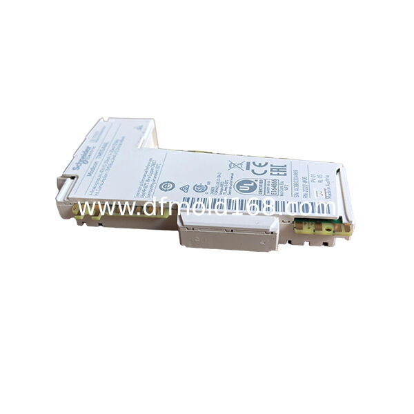
The TM5SE1IC02505 is a Modicon TM5 high-speed counter module designed for one incremental encoder channel with a maximum input frequency of 250 kHz.
It receives differential RS-422 encoder signals and processes the A, B and reference R channels independently from normal PLC scan-based digital inputs.
The module supports 16-bit and 32-bit counter values, making it suitable for position, length, speed and direction measurement in machines using incremental encoders.
A built-in encoder supply can provide either 5 V DC or 24 V DC at up to 300 mA, depending on the connected encoder requirement.
Two additional 24 V DC sink inputs are available for functions such as homing enable, reference control or other high-speed machine signals.
The TM5SE1IC02505 is specifically designed for incremental encoder counting. It does not decode absolute encoder protocols such as SSI, EnDat, BiSS or DRIVE-CLiQ.
Its defining combination is one 250 kHz incremental counter, RS-422 differential signal input, A/B/R reference channels and selectable 5 V or 24 V encoder power.
Key Features
- One incremental high-speed counter
- Maximum input frequency of 250 kHz
- RS-422 differential encoder interface
- A, B and reference R inputs
- 16-bit or 32-bit counting
- 5 V DC or 24 V DC encoder supply
- Maximum encoder supply current of 300 mA
- Two additional 24 V DC sink inputs
- Reference and preset functions
- Designed for TM5 motion-related measurement
Typical Applications
- Conveyor length measurement
- Rotary position tracking
- Machine speed monitoring
- Cut-to-length systems
- Packaging-machine indexing
Single Incremental Counter Channel
The TM5SE1IC02505 provides one dedicated high-speed counter channel.
The channel is intended for an incremental encoder with:
- Channel A
- Channel B
- Reference or index channel R
- Differential RS-422 signal pairs
- Compatible 5 V DC or 24 V DC supply
The A and B signals provide pulse count and direction information.
The R signal can be used as a reference or index pulse during homing and position-reset procedures.
250 kHz Counting Frequency
The maximum input frequency is 250 kHz.
This permits the module to receive up to 250,000 input signal cycles per second under the specified electrical conditions.
The practical maximum machine speed depends on:
- Encoder pulses per revolution
- Quadrature evaluation mode
- Mechanical transmission ratio
- Counter configuration
- Cable quality
- Electrical noise
- Controller task configuration
A 250 kHz module should not automatically be described as suitable for every high-speed encoder application.
The encoder output frequency at maximum machine speed must be calculated before selection.
Incremental Encoder Operation
An incremental encoder generates pulses as the shaft or machine axis moves.
The TM5SE1IC02505 uses these pulses to determine:
- Relative position
- Direction of travel
- Pulse count
- Rotational speed
- Linear speed
- Travel distance
- Reference position
Unlike an absolute encoder, an incremental encoder does not normally retain a unique mechanical position after complete power removal.
A homing or referencing process may therefore be required when the machine restarts.
A and B Quadrature Inputs
The A and B channels are phase-shifted encoder signals.
Their phase relationship allows the module to determine movement direction.
Typical interpretation includes:
- A leading B in one direction
- B leading A in the opposite direction
- Pulse edges increasing or decreasing the counter
- Optional quadrature multiplication depending on configuration
The configured evaluation mode affects the number of counter increments generated per encoder cycle.
Reference Input R
The R input receives the encoder reference or index pulse.
This signal may be used to:
- Establish a home position
- Reset the counter to zero
- Apply a preset value
- Verify one mechanical revolution
- Synchronize a machine axis
- Establish a repeatable reference point
The actual reference operation depends on the configured edge, enable input and preset parameters.
Preset and Homing Functions
The module supports reference-based preset operations.
A preset value can be applied after the configured reference event is detected.
Typical configuration elements include:
- Rising or falling reference edge
- Reference enable condition
- Low-active or high-active enable signal
- Preset counter value
- Reference input R
- Auxiliary digital input
This permits the counter to establish a known machine position during a homing sequence.
16-Bit and 32-Bit Counter Resolution
The counter can operate with 16-bit or 32-bit values.
16-Bit Counting
Suitable for smaller counting ranges.
Uses less numerical range.
32-Bit Counting
Supports much larger positive and negative count values.
More suitable for long travel, continuous rotation or high-resolution encoders.
The selected counter format must match the controller program and machine-position range.
RS-422 Differential Encoder Input
The encoder interface uses RS-422 differential signals.
Differential transmission uses complementary signal pairs and provides improved resistance to common electrical interference compared with single-ended pulse signals.
Typical differential pairs include:
- A and inverted A
- B and inverted B
- R and inverted R
The encoder must provide a compatible RS-422 output stage.
A standard 24 V push-pull or open-collector encoder should not be connected unless the electrical interface is confirmed to be compatible.
5 V or 24 V Encoder Supply
The module can provide encoder power at:
Maximum available current is:
300 mA
The selected supply must match the encoder nameplate and wiring specification.
Applying 24 V DC to a 5 V encoder can permanently damage the encoder.
Encoder Supply Protection
The internal encoder supply includes protection against:
- Short circuit
- Overcurrent
This protection is intended to protect the supply circuit under fault conditions.
It should not be used as a substitute for correct encoder wiring or load-current verification.
Encoder Input Filter
The encoder input filter is specified at no more than:
200 ns
This short filter time supports fast RS-422 pulse reception.
It also means wiring quality is important because electrical noise may be interpreted as encoder transitions if shielding and grounding are inadequate.
Two Auxiliary Digital Inputs
The module includes two additional 24 V DC digital inputs.
These inputs can support functions such as:
- Home-enable switch
- Reference-enable signal
- Limit detection
- Machine synchronization
- External control condition
The exact function depends on the software configuration.
Auxiliary Input Characteristics
Input Voltage Range
20.4–28.8 V DC
Input Current at 24 V DC
Approximately 3.3 mA
Input Resistance
Approximately 7.19 kOhm
Low-State Threshold
Below 6 V DC
High-State Threshold
Above 15 V DC
Input Cycle
2 Microseconds Maximum
These inputs are significantly faster than ordinary PLC inputs intended for slow switches and contacts.
Sink Input Logic
The auxiliary digital inputs use sink logic.
The connected sensor or switching device must provide the correct signal polarity and output architecture.
Before connection, verify:
- Sensor output type
- 24 V DC supply
- Common reference
- ON-state voltage
- OFF-state leakage
- Wiring polarity
Incorrect source/sink matching can prevent the input from switching correctly.
Shielded Cable Requirement
Shielded cable is required for encoder and high-speed signal connections.
Correct installation should include:
- Shielded twisted-pair encoder cable
- Correct differential pair assignment
- Continuous shielding
- Proper shield grounding
- Separation from motor power cables
- Separation from contactor wiring
- Minimal unnecessary junctions
Poor cable routing can cause false counts, lost pulses or incorrect direction detection.
Cable Grounding
The shield should be grounded according to the approved machine EMC plan.
Official guidance recommends single-point shield grounding unless the installation uses an appropriate equipotential ground plane.
Incorrect grounding may create:
- Ground-loop current
- Encoder noise
- Intermittent reference pulses
- Count errors
- Unstable position values
Do not leave the cable shield unconnected in electrically noisy machinery.
Not an Absolute Encoder Module
The TM5SE1IC02505 is not designed for absolute encoder protocols.
It does not directly support:
- SSI
- EnDat
- BiSS
- Hiperface
- DRIVE-CLiQ
- Resolver feedback
Those signal types require a compatible expert module, drive interface or encoder evaluation device.
Not a General Digital Input Module
Although the module includes two auxiliary digital inputs, its main purpose is high-speed incremental counting.
It should not be selected merely to add two standard machine inputs.
A standard TM5 digital input module is more appropriate when high-speed encoder processing is not required.
TM5SE1IC02505 vs Standard Digital Input Module
TM5SE1IC02505
Dedicated encoder counter.
250 kHz counting frequency.
RS-422 A/B/R interface.
16-bit or 32-bit position count.
Standard Digital Input Module
Reads normal 24 V DC sensor and switch states.
Does not provide quadrature encoder decoding.
Does not maintain a dedicated high-speed position counter.
The two module types are not interchangeable.
TM5SE1IC02505 vs TM5SE1IC01024
TM5SE1IC02505
One incremental counter.
250 kHz maximum frequency.
RS-422 encoder input.
5 V or 24 V encoder supply.
TM5SE1IC01024
One incremental counter.
100 kHz class.
Intended for a different input and encoder interface configuration.
TM5SE1IC02505 is selected when a 250 kHz RS-422 incremental encoder interface is required.
TM5SE1IC02505 vs TM5SE1IC20005
TM5SE1IC02505
250 kHz maximum counting frequency.
Suitable for medium-speed incremental encoder signals.
TM5SE1IC20005
Up to 4 MHz counting.
Intended for substantially higher encoder pulse frequencies.
A 4 MHz module is not automatically required unless the calculated encoder output exceeds the 250 kHz capacity.
TM5SE1IC02505 vs SSI Counter Module
TM5SE1IC02505
Incremental A/B/R pulse counting.
Relative position measurement.
Homing normally required after power loss.
SSI Module
Reads serial absolute position data.
Provides an absolute position word from the encoder.
Uses a different electrical interface and communication method.
Encoder type must be confirmed before choosing the module.
Power Requirements
Rated Supply Voltage
24 V DC
Supply Voltage Range
20.4–28.8 V DC
24 V DC I/O Segment Current Draw
63 mA
TM5 5 V Bus Current Draw
2 mA
Maximum Power Dissipation
1.51 W
Module Weight
Approximately 25 g
The encoder supply current must also be considered in the total station power budget.
Required Bus Base
The electronic module requires one of the following bus bases:
TM5ACBM11
Standard white TM5 bus base.
TM5ACBM15
TM5 bus base with address-setting capability.
The correct base depends on the station architecture.
Required Terminal Block
The specified terminal block is:
TM5ACTB12
12-Pin Terminal Block
The module, bus base and terminal block together form the complete installed TM5 slice.
Status LEDs
The module provides LEDs for:
- Run status
- Error status
- Counter input A
- Counter input B
- Reference input R
- Auxiliary digital inputs
These indicators support commissioning and fault diagnosis.
They confirm the electrical state detected at the module but do not prove that the machine mechanics or software scaling are correct.
Replacement Identification
Correct Model Number
TM5SE1IC02505
Product Type
One-Channel Incremental High-Speed Counter
Maximum Frequency
250 kHz
Encoder Interface
RS-422
Encoder Supply
5 V DC or 24 V DC
Counter Resolution
16-Bit or 32-Bit
Before replacement, confirm:
- Exact model number
- Incremental encoder type
- RS-422 electrical interface
- Encoder supply voltage
- Encoder current requirement
- Pulses per revolution
- Maximum machine speed
- A/B/R wiring
- Reference configuration
- Counter resolution
- Bus base
- Terminal block
- Shield grounding
- Controller project settings
Do not select the module only according to the 250 kHz value.
Installation Guidelines
Disconnect the TM5 station supply.
Disconnect the encoder and sensor supply.
Verify that all affected circuits are de-energized.
Record the A, B and R signal wiring.
Record the encoder supply voltage.
Label differential signal pairs.
Confirm the encoder output interface.
Confirm maximum encoder frequency.
Check the bus-base reference.
Check the terminal-block reference.
Install the electronic module securely.
Connect the encoder supply correctly.
Connect A, B and R differential pairs.
Connect auxiliary digital inputs if used.
Ground the cable shield according to the EMC plan.
Separate encoder cables from power wiring.
Restore the TM5 station supply.
Verify the run and error LEDs.
Rotate or move the encoder slowly.
Confirm count direction.
Verify reference-pulse operation.
Check the preset and homing function.
Test the machine at reduced speed.
Monitor the counter for missing or false pulses.
Return the machine to service after complete functional verification.
Installation should be completed by qualified automation personnel.
FAQ
Q1: What is TM5SE1IC02505?
A1: It is a Modicon TM5 single-channel incremental high-speed counter module with a maximum counting frequency of 250 kHz.
Q2: Which encoder type does it support?
A2: It supports a compatible incremental encoder with RS-422 differential A, B and reference R signals.
Q3: Does it support absolute encoders?
A3: No. It does not directly support SSI, EnDat, BiSS or other absolute encoder protocols.
Q4: What encoder supply voltage is available?
A4: The module can provide either 5 V DC or 24 V DC encoder power at up to 300 mA.
Q5: What is the counter resolution?
A5: It supports 16-bit or 32-bit counter values.
Q6: Does it have a reference input?
A6: Yes. The R input can be used for encoder reference and homing functions.
Q7: Does it include additional digital inputs?
A7: Yes. It includes two 24 V DC sink auxiliary inputs.
Q8: Is shielded cable required?
A8: Yes. Properly grounded shielded cable should be used for encoder and high-speed signal wiring.
Q9: Can it count a 4 MHz encoder signal?
A9: No. Its maximum specified counting frequency is 250 kHz. A higher-frequency expert module is required for faster signals.
Q10: What distinguishes TM5SE1IC02505 from a standard TM5 input module?
A10: It provides dedicated RS-422 quadrature encoder decoding, 250 kHz counting, reference processing and 16/32-bit position counting.

 Your message must be between 20-3,000 characters!