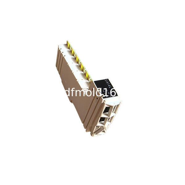
The TM5SAI6TH is a Modicon TM5 analog input module designed specifically for direct temperature measurement with J, K, N and S type thermocouples.
It provides six thermocouple input channels in one compact electronic module, making it suitable for machines that require several temperature-monitoring points within the same TM5 I/O station.
The module receives the low-level millivolt signal generated by each thermocouple and converts it into a digital temperature value for the controller.
Unlike a standard voltage or current input module, the TM5SAI6TH includes the signal conversion, thermocouple linearization and terminal-temperature compensation required for supported thermocouple sensors.
The module uses 16-bit analog-to-digital conversion and provides temperature values with a resolution of 0.1°C.
The configurable input time from 1 to 66.7 ms allows the user to balance measurement response and signal stability according to the thermal process.
The published thermocouple temperature ranges describe the temperatures that the connected sensor signal can represent. They do not describe the permitted ambient temperature of the TM5SAI6TH electronic module.
Key Features
- Six direct thermocouple inputs
- Supports J, K, N and S thermocouples
- 16-bit signal conversion
- 0.1°C temperature value resolution
- Configurable 1–66.7 ms input time
- Sigma-delta conversion
- Integrated thermocouple linearization
- Terminal-temperature compensation
- Shielded cable requirement
- Compact multi-zone temperature acquisition
Typical Applications
- Packaging-machine heaters
- Plastic processing equipment
- Sealing-temperature monitoring
- Industrial ovens
- Heated process machinery
Six-Channel Temperature Acquisition
The TM5SAI6TH provides six thermocouple input channels for monitoring multiple temperature zones.
Typical measurement points include:
- Sealing jaws
- Heating plates
- Extruder heating zones
- Mold temperature circuits
- Oven chambers
- Heated rollers
- Hot-air systems
- Thermal process equipment
Each channel must be configured for the thermocouple type connected to that input.
Supported Thermocouple Types
The module supports the following thermocouple types:
- Type J
- Type K
- Type N
- Type S
The thermocouple type selected in the controller configuration must match:
- The installed probe
- Extension cable material
- Polarity
- Required measurement range
- Process temperature
Connecting a different thermocouple type from the configured setting produces an incorrect temperature value.
Thermocouple Measurement Ranges
Official technical data specifies the supported signal-linearization ranges as follows:
Type J
-210 to 1200°C
Type K
-270 to 1372°C
Type N
-270 to 1300°C
Type S
-50 to 1768°C
These values describe the supported thermocouple measurement curves.
They do not mean that the TM5SAI6TH module can be installed in an environment at these temperatures.
Only the thermocouple sensing tip may be exposed to the measured process temperature. The electronic module remains installed in the TM5 station inside an approved control cabinet or machine enclosure.
Measurement Range vs Module Environment
Thermocouple Measurement Range
The temperature range represented by the sensor’s millivolt signal.
Module Operating Environment
The ambient conditions permitted around the TM5 electronic module itself.
For example, a Type K thermocouple may measure the temperature inside an industrial oven while the TM5SAI6TH remains installed remotely in a normal electrical cabinet.
Direct Millivolt Measurement
Thermocouples generate very small voltage signals that change according to the temperature difference between the measuring junction and reference junction.
The TM5SAI6TH accepts an input range of approximately:
±65.534 mV
It is therefore intended for low-level thermocouple signals rather than standard industrial transmitter signals.
The inputs must not be used for:
- 0–10 V transmitters
- ±10 V signals
- 0–20 mA signals
- 4–20 mA transmitters
- 24 V DC switching signals
These signals require a different analog or digital input module.
16-Bit Conversion
The module uses 16-bit analog-to-digital conversion.
This provides detailed digital representation of the thermocouple signal across the selected measurement range.
Temperature Value Resolution
0.1°C
The 0.1°C value is the displayed or reported temperature resolution.
It does not guarantee that the complete measurement system has an absolute accuracy of ±0.1°C.
Complete measurement accuracy also depends on:
- Thermocouple accuracy class
- Probe construction
- Extension cable
- Terminal-temperature compensation
- Ambient temperature
- Electrical interference
- Grounding
- Sensor position
- Installation quality
Configurable Input Time
The input time can be configured from:
1 to 66.7 ms
Shorter Input Time
Provides a faster response to temperature-signal changes.
May allow more signal noise to appear in the measured value.
Longer Input Time
Provides greater signal smoothing.
Produces a slower response to changing temperature.
The setting should be chosen according to the thermal process rather than automatically using the fastest option.
Sigma-Delta Conversion
The module uses sigma-delta conversion.
This conversion method is suitable for low-level measurement signals where noise rejection and stable signal conversion are important.
Thermocouple applications typically change more slowly than motion or pulse signals, so stable conversion is usually more important than extremely high sampling speed.
Input Filtering
The module includes a first-order low-pass input filter.
Filter Cutoff Frequency
500 Hz
The filter helps reduce interference caused by:
- Switching equipment
- Heater circuits
- Contactors
- Motor cables
- Variable-speed drives
- Ground noise
Shielded cable and correct cable routing are still required.
Terminal-Temperature Compensation
Thermocouple measurement depends on both the sensing-junction temperature and the temperature at the module terminals.
The TM5SAI6TH provides terminal-temperature compensation for the supported thermocouple inputs.
Official technical data specifies a terminal-temperature compensation tolerance of approximately:
±5°C after 10 minutes
For stable measurement:
- Allow the module to reach thermal equilibrium
- Avoid rapid airflow across the terminal block
- Keep high-heat modules away from the thermocouple slice
- Maintain stable cabinet ventilation
- Use the approved TM5 terminal arrangement
This compensation tolerance must be considered separately from the thermocouple sensor tolerance.
Input Accuracy
At an ambient temperature of 25°C, official maximum input deviations are approximately:
Type J
±0.10% of measurement
Type K
±0.11% of measurement
Type N
±0.11% of measurement
Type S
±0.17% of measurement
These values describe module input performance under stated conditions.
They do not include the complete error contributed by the thermocouple probe, extension cable and mechanical installation.
Non-Isolated Input Channels
The six thermocouple channels are not electrically isolated from one another.
This means:
- Inputs share the module’s internal measurement reference
- Significant ground-potential differences should be avoided
- Grounded thermocouples require careful system design
- Cable shielding is important
- Individual channel isolation must not be claimed
Where sensors operate at substantially different electrical potentials, isolated temperature transmitters may be required.
Module-to-Bus Separation
The input-side electronics have specified separation from the TM5 bus electronics.
However, the complete TM5 assembly references the power circuits to functional earth through EMC components.
The product should therefore not be marketed as a fully isolated six-channel measurement system.
Shielded Thermocouple Cable
Official documentation states that shielded cable is necessary.
Correct wiring should include:
- Matching thermocouple extension cable
- Correct positive and negative conductors
- Continuous thermocouple alloy path
- Suitable shielding
- Correct shield termination
- Separation from motor and heater-power cables
- Minimal intermediate junctions
Ordinary copper cable should not be substituted for the full thermocouple extension unless the approved compensation method is used.
Thermocouple Polarity
Thermocouples are polarity-sensitive.
Reversed conductors may cause:
- Temperature values to move in the wrong direction
- Incorrect low-temperature readings
- Unstable process control
- Misleading alarms
- Incorrect heater operation
Polarity should be verified from the sensor through to the module terminal block.
Open-Sensor Diagnostics
An open or disconnected thermocouple can result in an invalid or diagnostic input condition.
The controller program should handle:
- Open sensor
- Out-of-range value
- Invalid channel
- Broken cable
- Incorrect sensor type
- Unexpected temperature change
A heater-control system should not continue normal operation using an invalid temperature value.
TM5SAI6TH vs Standard Analog Input Module
TM5SAI6TH
Directly accepts J, K, N and S thermocouples.
Measures low-level millivolt signals.
Provides thermocouple linearization and terminal compensation.
Standard Voltage or Current Input Module
Accepts signals such as 0–10 V or 4–20 mA.
Used with industrial transmitters.
Does not directly replace a thermocouple module.
The two module types are not interchangeable.
TM5SAI6TH vs RTD Input Module
TM5SAI6TH
Designed for thermocouples.
Measures generated millivolt signals.
Supports wide and high-temperature measurement ranges.
RTD Input Module
Designed for resistance sensors such as Pt100 or Pt1000.
Measures resistance variation.
Often used for stable low- and medium-temperature measurement.
The installed temperature sensor determines the correct input module.
TM5SAI6TH vs Temperature Transmitter Input
Direct Thermocouple Connection
Thermocouple cable connects directly to TM5SAI6TH.
No separate transmitter is required.
Requires correct thermocouple wiring and grounding.
Temperature Transmitter
Converts the sensor signal into 4–20 mA or 0–10 V.
May provide channel isolation and longer transmission distance.
Requires a compatible standard analog input module.
The correct architecture depends on cable length, interference and isolation requirements.
Power Requirements
Rated Supply Voltage
24 V DC
Supply Voltage Range
20.4–28.8 V DC
24 V DC I/O Segment Current
38 mA
TM5 5 V Bus Current
2 mA
Maximum Power Dissipation
0.92 W
These values must be included in the complete TM5 station power calculation.
Replacement Identification
Correct Model Number
TM5SAI6TH
Product Type
Six-Channel Thermocouple Input Module
Supported Sensors
Thermocouple J, K, N and S
Conversion Resolution
16-Bit
Temperature Value Resolution
0.1°C
Before replacement, confirm:
- Exact model number
- Thermocouple type on each channel
- Existing channel assignments
- Sensor polarity
- Extension cable type
- Bus base
- Terminal block
- Input-time setting
- Controller hardware configuration
- Alarm and scaling parameters
- Shielding and grounding arrangement
Do not select a replacement only according to the number of analog inputs.
Installation Guidelines
Disconnect the TM5 station and associated heater circuits.
Verify that all relevant circuits are de-energized.
Record the existing channel assignments.
Record the thermocouple type used on each channel.
Label positive and negative sensor conductors.
Confirm the required bus base and terminal block.
Install the module securely.
Use matching thermocouple extension cable.
Maintain correct polarity.
Connect shields according to the machine grounding plan.
Keep thermocouple wiring away from power cables.
Restore the TM5 station supply.
Configure each channel for the correct sensor type.
Set the required input time.
Allow the module to reach thermal stability.
Compare each reading with a calibrated reference.
Test open-sensor and alarm handling.
Return the machine to operation only after functional verification.
Installation should be completed by qualified automation or instrumentation personnel.
FAQ
Q1: What is TM5SAI6TH?
A1: It is a Modicon TM5 analog input module with six channels for J, K, N and S thermocouples.
Q2: Do the published temperature ranges describe the module’s ambient temperature?
A2: No. They describe the supported thermocouple measurement and linearization ranges. The electronic module remains installed in an approved control cabinet environment.
Q3: Can it accept 4–20 mA signals?
A3: No. It is designed for low-level thermocouple millivolt signals.
Q4: What is its conversion resolution?
A4: It uses 16-bit analog-to-digital conversion.
Q5: Does 0.1°C resolution mean ±0.1°C accuracy?
A5: No. It is the temperature-value resolution. Complete system accuracy also depends on the sensor, wiring, compensation and installation.
Q6: Are the six channels individually isolated?
A6: No. The thermocouple channels are not isolated from one another.
Q7: Does it support Pt100 or Pt1000 sensors?
A7: No. Resistance temperature sensors require a compatible RTD input module.
Q8: Can the measurement response be adjusted?
A8: Yes. The input time can be configured from 1 to 66.7 ms.
Q9: Is shielded cable required?
A9: Yes. Official technical guidance states that shielded cable is necessary.
Q10: What distinguishes TM5SAI6TH from standard analog modules?
A10: It provides six direct thermocouple inputs with J, K, N and S linearization, 16-bit conversion and terminal-temperature compensation.

 Your message must be between 20-3,000 characters!