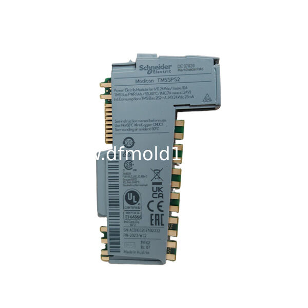
The TM5SDO4R is a Modicon TM5 digital output module equipped with four electromechanical relay outputs.
It is designed to switch compatible AC and DC loads that cannot be controlled directly by a standard 24 V DC transistor output module.
Each relay output can switch up to 5 A within the specified voltage and load limits.
The module supports 230 V AC and 30 V DC rated load circuits, making it suitable for contactor coils, interface relays, indicator devices and other industrial loads that require relay-contact switching.
The defining feature of the TM5SDO4R is its electrically operated relay output architecture.
Unlike the TM5SDO4TA high-current transistor module, the TM5SDO4R can switch both AC and DC circuits and does not require the load to share the TM5 24 V DC output supply.
However, the relay outputs are mechanical devices. Their switching speed is slower than transistor outputs, their contacts have a finite electrical life and external circuit protection is required.
The module does not provide internal short-circuit or overload protection for the switched load circuits.
Key Features
- Four electromechanical relay outputs
- Switches compatible AC or DC loads
- 230 V AC rated output
- 30 V DC rated output
- Maximum 5 A per output
- Maximum 10 ms relay response
- 20 million mechanical operations
- 500,000 electrical operations at 5 A
- 500 V AC channel-to-bus isolation
- Designed for mixed-voltage load switching
Typical Applications
- Contactor coil control
- Interface relay switching
- Warning lamps
- Heater control circuits
- Machine auxiliary loads
Four Relay Output Channels
The TM5SDO4R provides four controller-commanded relay outputs.
Typical connected loads may include:
- AC contactor coils
- DC contactor coils
- Interface relays
- Warning beacons
- Audible alarms
- Small heating circuits
- Auxiliary machine circuits
The suitability of each load must be checked against its voltage, steady-state current, inrush current and switching category.
AC and DC Load Capability
The relay contacts can switch compatible AC and DC circuits.
Rated AC Voltage
230 V AC
Permitted AC Range
184–276 V AC
Rated DC Voltage
30 V DC
Permitted DC Range
24–36 V DC
The load circuit uses an external power source. The module does not generate 230 V AC or 30 V DC.
5 A Per-Channel Rating
Each relay output is rated for a maximum current of 5 A under the specified conditions.
This value must not be interpreted as a universal rating for every load type.
The practical switching capacity depends on:
- Resistive or inductive load
- AC or DC operation
- Inrush current
- Switching frequency
- Power factor
- External suppression
- Ambient temperature
- Contact life requirement
Motors, transformers, lamps and capacitive loads can produce inrush currents much higher than their normal operating current.
Output Common Current
Official data specifies a maximum of 10 A per output common.
The common-terminal current and wiring must be checked according to the actual grouping of the output circuits.
Do not size the common conductor only from the current of one channel.
The combined current through a common terminal must remain within:
- Terminal rating
- Module rating
- Wire rating
- External fuse rating
- Applicable electrical standards
Relay Output vs Transistor Output
TM5SDO4R Relay Output
Can switch compatible AC and DC loads.
Uses mechanical contacts.
Has slower switching.
Provides separation between the control electronics and external load circuit.
Requires external load protection.
TM5SDO4TA Transistor Output
Switches 24 V DC loads only.
Uses solid-state electronics.
Provides faster switching.
Supports up to 2 A per channel and 4 A total.
Includes electronic short-circuit and thermal protection.
The two modules are intended for different load architectures.
10 ms Switching Response
The maximum switching times are:
Turn-On Time
10 ms
Turn-Off Time
10 ms
This is suitable for general machine-control loads such as contactors, alarms and auxiliary circuits.
It is not intended for:
- High-speed pulse generation
- Pulse-width modulation
- Fast valve timing
- Stepper control
- Motion-control pulses
A transistor output module should be selected for high-frequency switching.
Mechanical and Electrical Life
Mechanical Durability
Approximately 20 million operations
Electrical Durability
Approximately 500,000 operations at 5 A
Mechanical durability is measured without the same electrical load stress applied during normal switching.
Electrical life depends strongly on:
- Load current
- Load type
- Switching voltage
- Switching frequency
- Inrush current
- Arc suppression
- Ambient conditions
Reducing switched current can significantly extend contact life.
No Internal Short-Circuit Protection
The TM5SDO4R does not provide internal short-circuit protection for its load circuits.
An output short circuit may damage:
- Relay contacts
- Terminal wiring
- External supply
- Connected equipment
- Module conductors
Each load branch should use correctly rated external protection.
No Internal Overload Protection
The relay outputs do not include electronic overload monitoring.
The module does not automatically:
- Limit load current
- Shut down an overloaded channel
- Reset after a fault
- Report transistor-style thermal overload
External fuses or circuit breakers are required according to the load and wiring design.
External Fuse Requirement
Official wiring information specifies external protection for the switched circuits.
A typical documented arrangement uses:
5 A, 250 V, Time-Delay Fuse
Final fuse selection must consider:
- Load current
- Inrush current
- AC or DC breaking capacity
- Wire size
- Relay-contact rating
- Local electrical requirements
Do not replace a fuse with a larger value simply to prevent nuisance operation.
Inductive Load Protection
Contactors, solenoids and relays are inductive loads.
When switched off, they can generate a voltage transient that causes contact arcing and reduces relay life.
Suitable suppression may include:
- Flyback diode for DC coils
- RC snubber
- Varistor
- Manufacturer-approved suppression network
The suppression device must match the load voltage and required release time.
Contact Wear
Mechanical relay contacts wear every time they switch an electrical load.
Signs of contact deterioration may include:
- Increased contact resistance
- Intermittent switching
- Contact welding
- Delayed load operation
- Excessive heating
- Failure to open
For frequently cycled loads, a transistor output or external solid-state relay may provide a longer operating life.
Channel Isolation
The relay load circuits are separated from the internal TM5 bus electronics by specified insulation.
Channel-to-Bus Isolation
500 V AC RMS
However, official product data states that there is no insulation between output channels.
The module should therefore not be advertised as having four fully isolated output channels without confirming the exact terminal and common arrangement.
External Load Supply
Every switched load requires an appropriate external supply.
Examples include:
- 230 V AC cabinet supply
- 24 V DC auxiliary supply
- 30 V DC control circuit
- Separately protected machine circuit
The relay output functions as a controlled electrical contact. It does not generate load voltage.
Mixed-Voltage Applications
Relay technology makes it possible to switch different types of load circuits within the module’s approved wiring architecture.
Before using multiple voltages in the same module, confirm:
- Terminal grouping
- Insulation requirements
- Creepage and clearance
- Common-terminal arrangement
- Wiring segregation
- Local standards
- Approved wiring diagram
Do not mix hazardous and extra-low voltage circuits unless the official system design and applicable regulations permit it.
Module Power Consumption
The relay coils and internal electronics are supplied from the TM5 bus.
TM5 Bus Current Draw
Approximately 160 mA at 5 V DC
Maximum Power Dissipation
Approximately 2.3 W
The switched load current does not come from the TM5 bus. It is supplied by the external AC or DC load circuit.
Operating Environment
Horizontal Installation Without Derating
-10 to 55°C
Horizontal Installation With Derating
-10 to 60°C
Vertical Installation
-10 to 50°C
Storage Temperature
-40 to 70°C
These values describe the ambient temperature around the module, not the temperature of the controlled load.
TM5SDO4R vs TM5SDO4TA
TM5SDO4R
Four relay outputs
230 V AC or 30 V DC load switching
5 A maximum per channel
10 ms maximum response
No internal short-circuit protection
TM5SDO4TA
Four transistor outputs
24 V DC loads only
2 A maximum per channel
300 microsecond maximum response
Electronic short-circuit and thermal protection
TM5SDO4R is selected for voltage flexibility and relay-contact switching.
TM5SDO4TA is selected for faster 24 V DC actuator control.
TM5SDO4R vs TM5SDO4T
TM5SDO4R
Relay output technology
AC or DC loads
5 A per output
Slower mechanical switching
TM5SDO4T
24 V DC transistor outputs
0.5 A per output
Fast solid-state switching
No mechanical contact wear
The correct module depends on the load voltage and switching frequency.
TM5SDO4R vs TM5SDO2R
TM5SDO4R
Four relay outputs
Higher channel count
Suitable for four auxiliary load circuits
TM5SDO2R
Two relay outputs
Lower channel count
Suitable for smaller relay-output requirements
Confirm the terminal block and output mapping before replacing one module with another.
Not a Power Distribution Module
The TM5SDO4R should not be described as a power distribution node.
It does not:
- Supply the TM5 I/O power segment
- Generate TM5 bus power
- Replace TM5SPS1 or TM5SPS2
- Distribute 24 V DC to downstream modules
- Perform load-current management
It receives controller commands and opens or closes relay contacts.
Not a Safety Output Module
TM5SDO4R is a standard machine-control output module.
It must not be described as:
- Fail-safe output
- Safety relay
- Emergency-stop module
- SIL-rated output
- Performance Level output
Safety-related loads require an approved safety architecture.
Replacement Identification
Correct Model Number
TM5SDO4R
Product Type
Four-Channel Relay Output Module
Rated Load Voltage
230 V AC or 30 V DC
Maximum Current
5 A per Output
Output Technology
Electromechanical Relay
Before replacement, confirm:
- Exact model number
- Number of relay outputs
- Load voltage
- Load current
- Inrush current
- AC or DC circuit
- Output common arrangement
- Terminal block
- Bus base
- External fuse
- Suppression device
- Controller output mapping
Do not select a replacement only by the four-channel count.
Installation Guidelines
Disconnect the TM5 station supply.
Disconnect all external load supplies.
Verify that AC and DC circuits are de-energized.
Record the existing output assignments.
Label all common and switched conductors.
Confirm each load voltage and current.
Check the load inrush current.
Verify the external fuse rating.
Verify inductive-load suppression.
Confirm the bus base and terminal block.
Install the electronic module securely.
Connect wiring according to the approved diagram.
Maintain separation between voltage classes.
Restore the TM5 supply.
Restore each load supply safely.
Test outputs one at a time.
Verify contactor, lamp or relay operation.
Check for abnormal heating or contact noise.
Return the machine to service after functional verification.
Installation should be completed by qualified automation and electrical personnel.
FAQ
Q1: What is TM5SDO4R?
A1: It is a Modicon TM5 digital output module with four electromechanical relay outputs.
Q2: Can it switch AC loads?
A2: Yes. It is rated for compatible loads around 230 V AC within the specified voltage range.
Q3: Can it switch DC loads?
A3: Yes. It supports compatible DC load circuits rated around 30 V DC.
Q4: What is the maximum current per output?
A4: The maximum stated current is 5 A per output under approved load conditions.
Q5: Is it a transistor output module?
A5: No. It uses mechanical relay contacts.
Q6: Does it have short-circuit protection?
A6: No. External circuit protection is required.
Q7: Does it have overload protection?
A7: No. The load circuit must use correctly selected external protection.
Q8: How fast does it switch?
A8: Maximum turn-on and turn-off times are approximately 10 ms.
Q9: Can it be used for high-speed pulse outputs?
A9: No. Mechanical relay outputs are not suitable for high-frequency pulse control.
Q10: What distinguishes TM5SDO4R from TM5SDO4TA?
A10: TM5SDO4R switches AC or DC loads through relay contacts, while TM5SDO4TA provides faster, electronically protected 24 V DC transistor outputs.

 Your message must be between 20-3,000 characters!