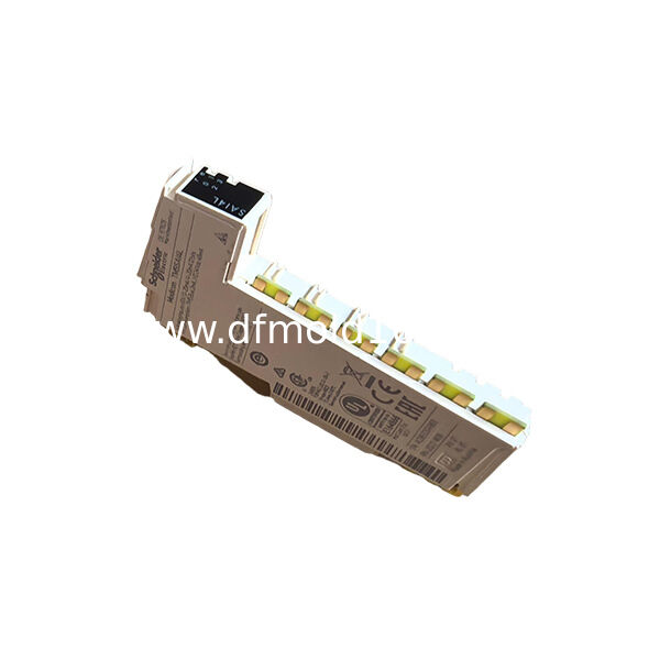
The TM5SDO4TA is a Modicon TM5 digital output module designed to switch four 24 V DC actuator loads.
Each transistor output can deliver up to 2 A, while the combined current of all four outputs must remain within the module’s 4 A total-output limit.
This high-current-per-channel configuration distinguishes the TM5SDO4TA from standard low-current digital output modules that are intended mainly for indicator lamps, interface relays or smaller electronic loads.
The module is suitable for direct control of compatible solenoid valves, contactor coils, DC actuators and other industrial loads that require more current than a typical 0.5 A output channel can provide.
Its electronic protection includes short-circuit, overload and thermal monitoring. After the fault condition is removed and the internal temperature permits, the affected output can reset automatically.
The TM5SDO4TA uses solid-state transistor outputs rather than mechanical relay contacts. This supports faster switching and eliminates mechanical contact wear, but the module is intended for DC loads and does not provide dry relay contacts.
Key Features
- Four 24 V DC transistor outputs
- Maximum 2 A per output
- Maximum 4 A total module current
- Fast 300 microsecond switching
- Up to 500 Hz with resistive loads
- Short-circuit protection
- Overload and thermal protection
- Automatic fault reset
- Reverse-polarity protection
- Suitable for higher-current DC actuators
Typical Applications
- Solenoid valve control
- Contactor coil switching
- Pneumatic actuator systems
- Packaging machinery
- Material handling equipment
Four High-Current Output Channels
The TM5SDO4TA provides four independently commanded digital output channels.
Typical connected loads include:
- 24 V DC solenoid valves
- Pneumatic valve manifolds
- Contactor coils
- DC brake coils
- Industrial indicator devices
- Small DC actuators
- Interface relays
Although each output is rated for up to 2 A, the total current of all active channels must not exceed 4 A.
Per-Channel and Total Current Limits
Maximum Current per Output
2 A
Maximum Total Module Current
4 A
This means four channels cannot each deliver 2 A simultaneously.
Example combinations within the 4 A total limit may include:
- Two outputs at 2 A each
- Four outputs at 1 A each
- One output at 2 A and two outputs at 1 A
- Other combinations whose total remains at or below 4 A
Load current must be calculated using the actual steady-state and startup current of every connected actuator.
24 V DC Transistor Outputs
The module uses solid-state transistor switching for 24 V DC loads.
The permitted output-voltage range is:
Minimum
20.4 V DC
Maximum
28.8 V DC
The module does not generate 24 V DC. It switches power supplied through the TM5 I/O power segment.
Transistor Output vs Relay Output
TM5SDO4TA Transistor Output
Designed for 24 V DC loads
Fast switching
No mechanical contact wear
Protected electronically
No dry contact
Relay Output Module
Can switch electrically isolated contact circuits
May support AC or DC loads depending on rating
Slower mechanical operation
Subject to contact wear
TM5SDO4TA should not be promoted as a relay output module.
Fast Switching Response
The maximum switching times are:
Turn-On Time
300 Microseconds
Turn-Off Time
300 Microseconds
This makes the module suitable for relatively fast machine-control signals such as:
- Timed valve actuation
- Product-diverter commands
- Repetitive actuator cycling
- Short process-control pulses
- High-speed machine sequencing
The complete response time also depends on controller scan time, bus cycle and actuator mechanics.
500 Hz Resistive Load Switching
For suitable resistive loads, the maximum switching frequency is 500 Hz.
This value should not be applied automatically to inductive loads.
Solenoid valves, contactor coils and other inductive devices require evaluation according to:
- Load inductance
- Load resistance
- Operating current
- Switching duty
- Suppression circuit
- Ambient temperature
The permitted operating frequency for an inductive load may be significantly lower.
Short-Circuit Protection
Each output is protected against short circuits within the specified operating limits.
A short circuit may cause:
- Output shutdown
- Channel error status
- Thermal protection activation
- Temporary interruption of the connected load
The short-circuit peak current can reach up to 12 A before the protective function reacts.
Overload and Thermal Protection
The module monitors excessive current and internal temperature.
Protection may activate if:
- A load draws more than the permitted current
- Multiple outputs exceed the 4 A total limit
- An actuator has an internal fault
- Switching duty causes excessive heating
- Cabinet temperature is too high
- Wiring is shorted
The cause of the overload must be corrected before normal operation resumes.
Automatic Output Reset
After a short circuit or overload is removed, the module supports automatic reset.
The minimum reset period is approximately 10 ms, but the actual recovery time depends on internal temperature.
Repeated automatic resetting should not be treated as normal operation.
If the output repeatedly cycles between fault and reset, inspect:
- Load current
- Wiring
- Supply voltage
- Output duty cycle
- Cabinet temperature
- Actuator condition
Reverse-Polarity Protection
The module includes reverse-polarity protection for the applicable supply connection.
This protection reduces the risk of immediate damage from incorrect polarity, but correct wiring must still be verified before energization.
Do not rely on protective circuitry as a substitute for proper installation.
Inductive Load Protection
Inductive loads generate voltage when switched off.
The TM5SDO4TA includes output clamping, with a typical clamping voltage of approximately 50 V DC.
Appropriate actuator protection may still be required depending on:
- Coil inductance
- Switching frequency
- Cable length
- Required release speed
- Manufacturer instructions
External suppression devices must be selected so they do not interfere with output operation or actuator release time.
Output Voltage Drop
At a rated load current of 2 A, the maximum output voltage drop is approximately 0.5 V DC.
This voltage drop should be considered when:
- Long field cables are used
- The supply voltage is near its lower limit
- The actuator has a narrow operating-voltage range
- Several wiring connections add resistance
Measure voltage at the load terminals under operating conditions when troubleshooting weak actuator operation.
Output Leakage Current
The output leakage current in the OFF state is approximately 5 μA.
This very small current can still be relevant for highly sensitive electronic loads.
If a connected device remains faintly energized or falsely detects an ON condition, verify its minimum load and leakage-current tolerance.
One-Wire, Two-Wire and Three-Wire Loads
The module supports 1-wire, 2-wire and 3-wire load arrangements according to the approved wiring diagram.
This enables different actuator connection methods within a modular TM5 station.
Before wiring, confirm:
- Load type
- Output terminal
- 0 V reference
- 24 V DC actuator supply
- Common distribution
- Protective conductor size
- External suppression requirements
Unused terminals marked as no connection must not be wired.
Output Status Monitoring
The module provides output-command and output-status information through the TM5 system.
The controller can monitor status information associated with each output.
This helps identify conditions such as:
- Normal output operation
- Detected output fault
- Invalid power supply
- TM5 bus condition
- I/O data validity
The exact diagnostic behavior depends on the controller program and hardware configuration.
Channel Isolation
The four outputs are not individually isolated from one another.
They share the same field-side supply arrangement.
The module provides separation between the TM5 bus-powered electronics and the I/O power-segment circuitry according to the system design, but this should not be described as four galvanically isolated output channels.
TM5SDO4TA vs Standard 0.5 A Output Module
TM5SDO4TA
Four outputs
Up to 2 A per channel
4 A maximum total
Suitable for higher-current actuators
Standard Low-Current Output Module
Often provides more channels
Lower current per channel
Better suited to indicators, small relays and electronic inputs
The correct choice depends on actuator current rather than channel count alone.
TM5SDO4TA vs TM5SDO8TA
TM5SDO4TA
Four outputs
2 A maximum per channel
Three-wire-oriented high-current configuration
4 A total output limit
TM5SDO8TA
Eight outputs
Higher channel density
Different wiring and total-current arrangement
TM5SDO4TA is more suitable when fewer but higher-current output channels are required. TM5SDO8TA is selected when additional output density is more important.
TM5SDO4TA vs Safety Output Module
TM5SDO4TA
Standard digital output module
Used for normal machine-control functions
Safety Output Module
Designed for validated safety-related load switching
Requires compatible safety controller and project
TM5SDO4TA must not be used as a certified fail-safe output merely because it controls a contactor or machine interlock.
System Power Requirements
The module draws power from:
- TM5 internal 5 V DC bus
- 24 V DC I/O power segment
Maximum TM5 Bus Current
32 mA
Maximum 24 V DC I/O Segment Current Used by Module Electronics
21 mA
Maximum Power Dissipation
2.10 W
The connected actuator current is additional and must be included in the I/O power-segment budget.
Wiring Requirements
Because the module can switch relatively high current, conductor size is important.
Use wiring suitable for:
- Maximum channel current
- Total common current
- Ambient temperature
- Terminal rating
- Cable length
- Applicable electrical regulations
For 2 A output wiring, official guidance specifies conductors of at least 0.5 mm² under the stated installation conditions.
Replacement Identification
Correct Model Number
TM5SDO4TA
Product Type
Four-Channel Transistor Output Module
Output Voltage
24 V DC
Maximum Current per Channel
2 A
Maximum Total Current
4 A
Output Protection
Short Circuit, Overload and Thermal
Before replacement, confirm:
- Exact model number
- Number of output channels
- Transistor output requirement
- Load current per channel
- Combined load current
- Actuator voltage
- Wiring type
- Terminal block
- Bus base
- Output mapping
- Existing protection devices
Do not select a replacement only according to the TM5 housing or the number of terminals.
Installation Guidelines
Disconnect the TM5 station and actuator supply.
Verify that all output circuits are de-energized.
Record the existing output assignments.
Label all actuator wires.
Confirm each load current.
Calculate the combined output current.
Verify the bus base and terminal block.
Install the electronic module securely.
Connect the 24 V DC I/O power segment.
Connect each actuator according to the approved diagram.
Install required inductive-load protection.
Check polarity and conductor size.
Restore power.
Test outputs individually.
Monitor output fault status.
Check module temperature under load.
Verify the total current during simultaneous operation.
Return the machine to service after functional testing.
Installation should be completed by qualified automation personnel.
FAQ
Q1: What is TM5SDO4TA?
A1: It is a Modicon TM5 digital output module with four 24 V DC transistor outputs.
Q2: How much current can each output provide?
A2: Each output can provide up to 2 A.
Q3: Can all four outputs provide 2 A simultaneously?
A3: No. The maximum combined output current for the module is 4 A.
Q4: Is it a relay output module?
A4: No. It uses protected solid-state transistor outputs.
Q5: Can it control solenoid valves?
A5: Yes, provided the voltage, steady-state current, inrush current and inductive switching requirements remain within the module limits.
Q6: What are the switching times?
A6: Maximum turn-on and turn-off times are both 300 microseconds.
Q7: Does it have short-circuit protection?
A7: Yes. It includes short-circuit, overload and thermal protection.
Q8: Does the output recover automatically after an overload?
A8: Yes. Automatic reset is supported after the fault is removed and the internal temperature permits recovery.
Q9: Are the four outputs individually isolated?
A9: No. The output channels are not isolated from one another.
Q10: What distinguishes TM5SDO4TA from other TM5 output modules?
A10: Its defining combination is four outputs, 2 A per-channel capacity, a 4 A module limit, fast transistor switching and integrated electronic protection.

 Your message must be between 20-3,000 characters!